Configuring the HDSPe AoX-M
The HDSPe hardware offers a number of helpful, well thought-of practical functions and options which affect how the card operates - it can be configured to suit many different requirements.
-
Latency (Buffer size)
-
Optional Channel Limitation
-
WDM Device Configuration
-
Current sample rate
-
Synchronization behavior
-
Configuration of digital I/Os
-
Input selection
-
State of input signals
Any changes made in the Settings dialog are applied immediately - confirmation (e.g. by clicking on OK or exiting the dialog) is not required.
| Settings should not be changed during playback or record if it can be avoided, as this can cause unwanted noise. |
Also, please note that even in 'Stop' mode, several programs keep the recording and playback devices open, which means that any new settings might not be applied immediately.
The status displays at the bottom of the dialog box give the user precise information about the current status of the system, and the status of all digital signals.
The tab About provides information about the current driver version of the HDSPe AoX-M.
Revealing the Settings Dialog
The HDSPe AoX-M is configured through its dedicated settings dialog.

The panel 'Settings' can be opened by clicking on the hammer symbol  in the task bar notification area.
The mixer of the interface, TotalMix FX, can be opened by clicking on the knob symbol  in the task bar notification area.
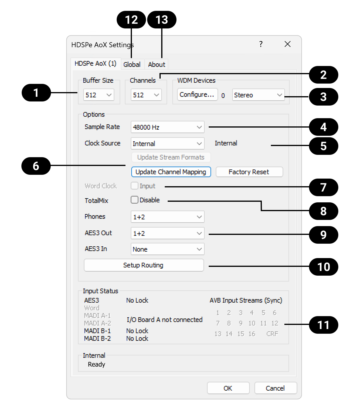
Settings Dialog Overview
|
Buffer Size |
|
TotalMix Disable |
|
Channels |
|
Phones and AES3 Routing |
|
WDM Devices |
|
Routing Setup |
|
Sample Rate |
|
Digital Signal Input Status |
|
Clock Source |
|
'Global' Tab |
|
AVB related controls |
|
'About' Tab |
|
Word Clock Input |
Buffer Size
The setting Buffer Size determines the latency between incoming and outgoing ASIO and WDM data and affects system stability. While ASIO can use any offered buffer size, WDM is limited to 512 samples. The driver handles this automatically, higher settings are only applied to ASIO while WDM will stay at 512 samples internally.
Channels
Sets the number of available channels of the driver. It can be useful to reduce the number of channels if the driver is used in a system with limited resources.
 WDM Devices
Allows to freely set which I/Os are available as WDM devices, if these are stereo or multi-channel devices (up to 8 channels), and if one or multiple of the currently active WDM devices should have the Speaker property. More details are found in chapter Configuring the HDSPe AoX-M.
Clock Mode
 Sample Rate
In general, sampling rate should be set using the MILAN Manager. This setting only applies if the network is not connected. It configures the sample rate of all WDM devices to the same value. ASIO programs can still attempt to set the sample rate individually.
During record/playback the selection is greyed out, so no change is possible.
 Clock Source
In a MILAN network, the HDSPe AoX-M can act as a media clock leader or as a follower. If another entity in the network generates the media clock for the network, select 'AVB CRF Input Stream' as clock source and use MILAN Manager to connect the corresponding stream automatically. If a clock source other than 'AVB CRF Input Stream' is selected, the clock source is used as a reference for all digital input and output signals. Other entities on the network should use the HDSPe AoX-M CRF output stream to synchronize to the card.
 AVB Related Controls
Most of the MILAN® or AVB related settings must be configured externally using an ATDECC controller such as MILAN Manager. However, basic convenience functions are included to accelerate re-configuration of the endpoint after a sampling rate or stream size change.
 Word Clock A Connector
The Word Clock BNC jacks on the optional MADI extension boards act as outputs by default. The checkbox 'input' can be used change the Word Clock BNC of the expansion module in Slot A to act as an input instead. The incoming signal can then act as the clock source of the card.
 TotalMix Disable
Disables TotalMix FX. This is useful if the driver is used in a system where TotalMix FX is not needed.
 Phones and AES3 Routing
The source channels of the Phones and AES3 outputs can be set here. They can either be a submix created in TotalMix FX, or one of the additional software playback channels of the driver. If selecting channels for the AES3 input, they replace the currently selected Milan® or MADI input channels.
 Routing Setup
The routing setup dialog is divided into Input and Output Routing. The input routing is used to replace blocks of 64 network input channels with signals from the MADI extension modules. The output routing is used to copy any block of 64 playback channels from the driver to the MADI extension modules.
 Input Status
Displays the state of the current input signal:
-
Clock state (No Lock, Lock, Sync)
-
Sample rate (coarse)
RME’s exclusive SyncCheck technology provides an easy to use indicator of the current clock status. The clock state column indicates whether no signal (No Lock), a valid signal (Lock) or a valid and synchronous signal (Sync) is present at each of the digital clock source inputs.
 Global Tab
Provides details about the installed card(s) as well as additional driver configuration options.
 About Tab
Driver version and copyright disclaimers.
WDM Devices
The WDM (Windows Driver Model) driver provides a method for Windows to access the inputs and outputs of the HDSPe AoX-M. The driver therefore allows sound to be played back from the operating system itself (notification sounds etc.) and from a wide range of multimedia applications. It can be used in addition or as an alternative to the ASIO driver that provides better performance for multichannel applications. WDM supports advanced audio configurations, including complex speaker setups for surround sound and immersive audio playback.
| Both the ASIO and WDM driver are present and active at the same time. |
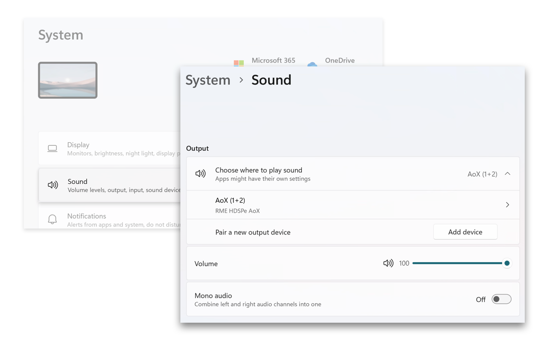
WDM devices typically consist of a few channels, for example to represent a pair of headphones or a set of speakers. The Settings Dialog is used to configure one or more separate WDM devices, which then appear for further configuration in Windows' Sound Settings.
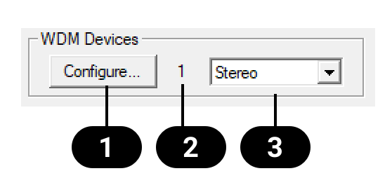
The WDM Devices section of the Settings Dialog has one button to enter the configuration dialog , a status display showing the number of currently enabled WDM devices , and a dropdown field to select between Stereo or Multi-Channel devices.
The number represents both record and playback devices, so '1' means one input and one output device.
Create and Modify WDM Devices
-
Select 'Stereo' or 'Multi-Channel' from the drop down menu. This sets the following configuration dialog to display only multi-channel or stereo devices.
-
Open the configuration dialog by pressing Configure… in the settings panel.
-
Activate any number of devices from the list.
-
Optionally, use the checkbox All to activate or deactivate all devices simultaneously.
-
Press OK to confirm changes and reload the WDM devices.
| Activating all devices at once can freeze the operating system for a considerable amount of time. Activate only the devices you need. |
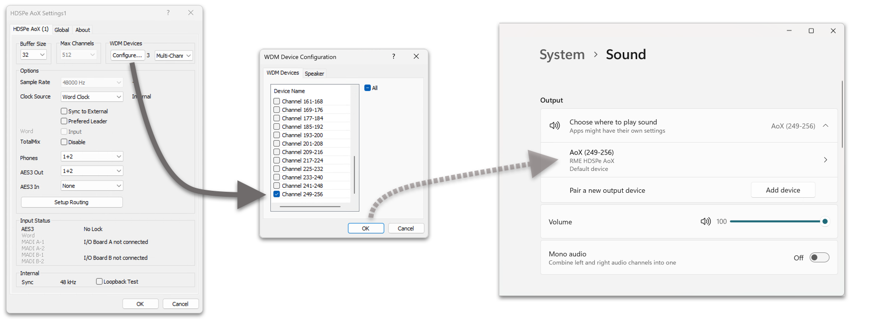
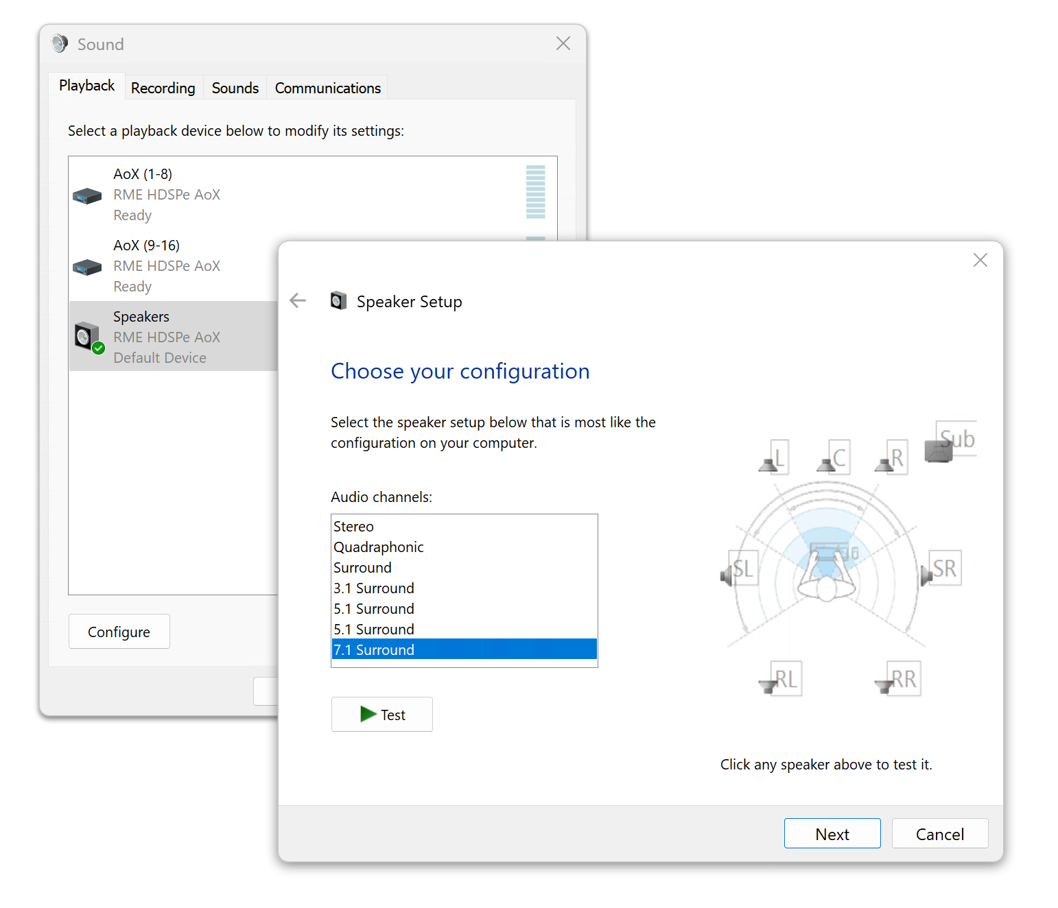
Using a multi-channel WDM device allows for the use of multi-channel playback with specialized software as well as Surround sound from DVD or Blu-Ray player software.
-
Select 'Multi-Channel' from the WDM Devices dropdown.
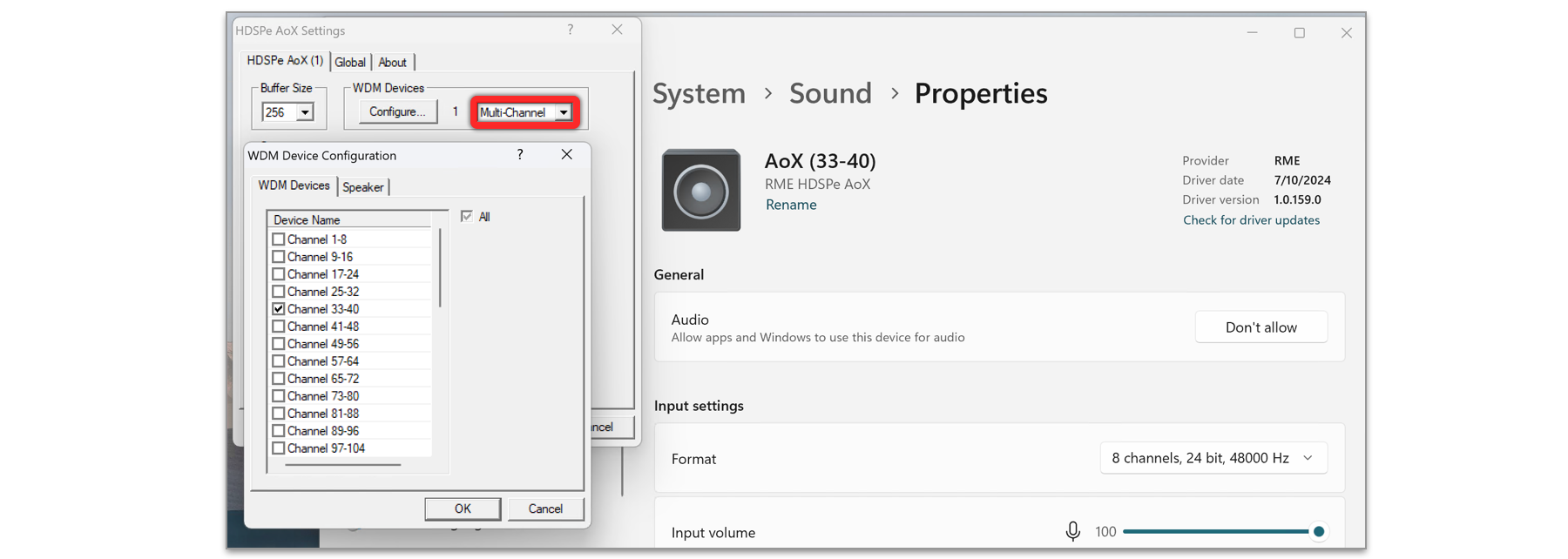
-
Press Configure….
-
Choose the desired multi-channel device. In the example shown, the device Channel 33-40 is selected for multi-channel playback.
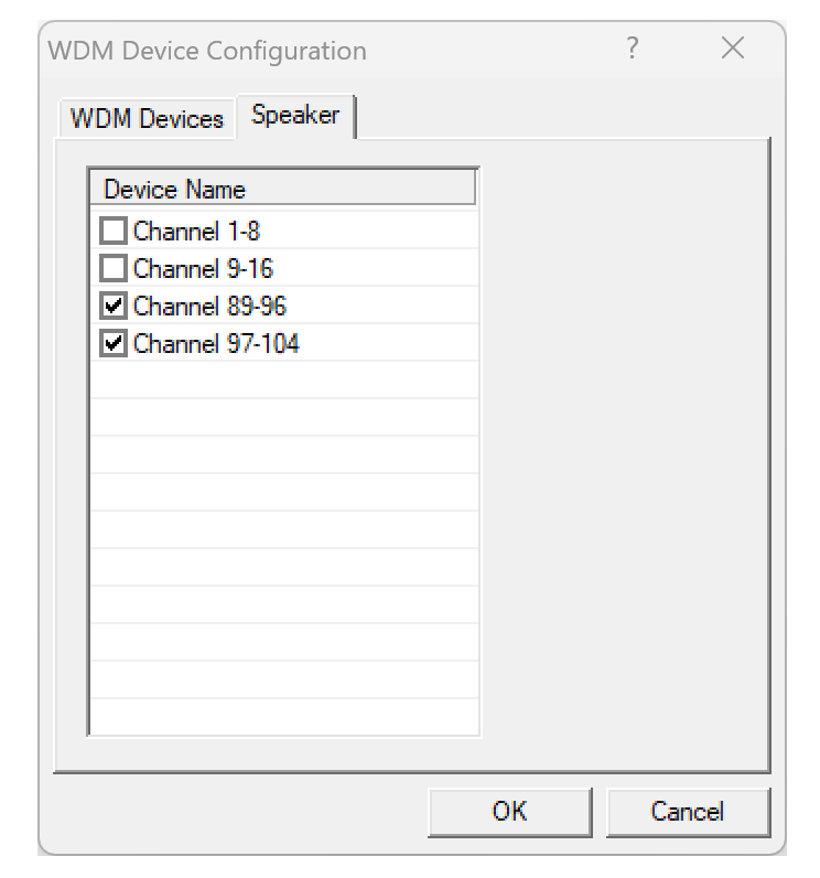
Configuring the multi-channel WDM device to a specific surround mode in the Windows Sound control panel requires the device to have the Speaker property. This can be set on the Speaker tab.
-
While in the configuration dialog, switch to the Speaker tab. Active WDM devices listed as shown below:
-
Select the devices to assign the Speaker property.
-
Optionally, use the checkbox All to assign or remove the Speaker property for all devices simultaneously.
-
Use the Windows configuration dialog to set the preferred surround setup.
| Defining more than one device as Speaker usually makes no sense, as Windows does not number or rename speaker devices, making them indistinguishable. |
Global Tab
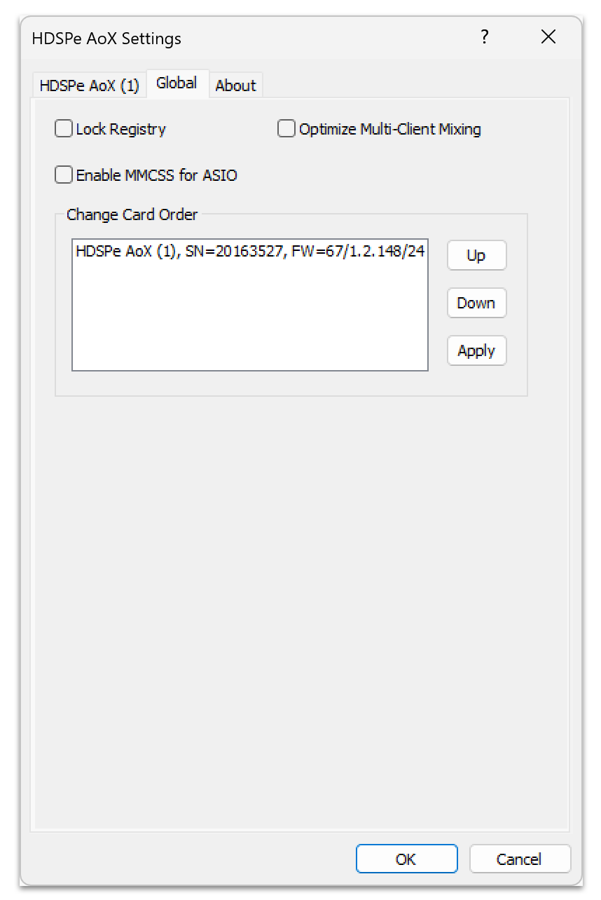
This tab includes several options that work on all currently installed cards.
Lock Registry
Default: off. Checking this option brings up a dialog to enter a password. Changes in the Settings dialog are no longer written to the registry. As the settings are always loaded from the registry when starting the computer, this method provides an easy way to define an initial state of the HDSPe AoX-M.
Optimize Multi-Client Mixing
Default: off. Checking this option removes short noise bursts when multi-client playback starts but will also introduce some additional CPU load.
Enable MMCSS for ASIO
Enable MMCSS for ASIO activates support with higher priority for the ASIO driver (Default Off)
| At this time, activating this option seems to be useful only with the latest Cubase/Nuendo at higher load. With other software this option can decrease performance. The change becomes active after an ASIO reset. Therefore, it is easy to quickly check which setting works better. |
Change Card Order
This dialog lists all cards currently installed in the system and controlled by the driver. Their order can then be changed by selecting a card and using the up/down arrows. Confirm the operation with the Apply button. This feature comes in handy if different cards are installed and a specific one of them should always be the first in the ASIO channel list.
At the end of each card info line its current firmware version is shown (Revision).
Clock Synchronization
In digital systems, all devices must function as either a Leader (clock source) or Follower (clock receiver). If multiple devices are connected, there must always be one Leader Clock. A digital system can only have one Leader clock at any time.
The SyncCheck technology from RME allows users to easily monitor and verify the current clock status. The Input Status display shows whether there is a valid signal (Lock or No Lock) for each input (Word, MADI, AES, or Sync In). The display also indicates if the signal is valid and synchronized (Sync).
The Clock Source setting allows you to define a preferred input for synchronization. If a valid signal is present on the preferred input, it is used as the sync source. If no valid signal is detected, the system scans the other inputs in sequence. If no inputs have a valid signal, HDSPe AoX-M automatically switches to Leader clock mode.
When using WDM, the card sets the sample rate. If the sample rate of the digital signal and the system do not match, an error may occur. For example, if a 48 kHz signal is detected at the Word Clock input, but the card is set to 44.1 kHz, a red error message will appear, prompting the user to manually set the sample rate to 48 kHz.
When using ASIO, the audio software sets the sample rate, so such mismatches are rare. In follower mode, the external sample rate takes priority, and the system will not allow incompatible settings. For instance, feeding 44.1 kHz prevents the ASIO software from setting 48 kHz unless the clock mode is switched to Leader/Internal.
SyncCheck provides a simple way to verify whether all connected digital devices are properly configured. With SyncCheck, users can easily resolve one of the most common and complex issues in digital studio setups.
AVB Configuration Commands
The settings dialog offers three convenience functions to quickly re-configure common options of the internal AoX-M AVB entity.
Update Stream Formats
Incoming and outgoing stream formats should be matched between talker and listener. However, some AVB controllers do not adjust the stream formats when changing the sampling rate of the system. This leads to a mismatch between the stream formats of talker and listener, and subsequently it could prevent a connection of streams.
Update Stream Formats becomes active if the sampling rate has been changed, but the incoming and outgoing stream formats do not match the new sampling rate. Pressing this button will re-configure all incoming and outgoing stream formats to match the configured sampling rate of the HDSPe AoX-M.
| Stream formats cannot be adjusted if the streams are currently connected. Please use an external controller to first disconnect the streams. |
Update Channel Mapping
AVB uses "dynamic mappings" for input and outputs to route the incoming and outgoing stream channels.
As an example, in its default configuration, 128 audio channels that reach the PCIe driver are mapped to contain 16 streams of 8 channels each in a consecutive sequence.
If the first stream is now adjusted to contain 16 audio channels, those additional eight channels are not automatically inserted between input channels eight and nine - unless the external ATDECC controller performs this adjustment automatically (at the time of writing, common ATDECC controllers require this to be configured manually).
As another example, the ATDECC controller might offer a user-facing feature to "Delete all dynamic mappings" of an entity. This would remove all channel mappings from incoming streams to the PCIe driver and therefore no audio would reach the software and TotalMix.
Finally, it is even possible to create very complex routings, for example routing channel 3 and 4 of streams 5 and 9 to inputs 1-4 of the HDSPe AoX-M. Such a routing can easily become confusing.
The button Update Channel Mapping scans the incoming and outgoing stream sizes and generates the corresponding dynamic mappings. They become active right away. This is particularly convenient when using 16- or 32-channel stream formats.
| This feature may shift channels unexpectedly as described in the example above. |
Factory Reset
The Factory Reset button reverts the AVB entity to its default MILAN® configuration (16 streams of 8 channels AAF at 48 kHz sampling rate).
| Any changes made to the entity - such as entity name, stream presentation time offset, stream formats, mappings, and various other settings, will be deleted. |